- #Nand gate ic 7400 datasheet serial
- #Nand gate ic 7400 datasheet full
- #Nand gate ic 7400 datasheet series
Note: Unlike other Arduino boards, the Arduino Due board runs at 3.3V.

There are also some cool features like DACs, Audio, DMA, an experimental multi tasking library and more.
#Nand gate ic 7400 datasheet serial
It increases the computing power available to Arduino users keeping the language as compatible as possible so that many programs will be migrated in a matter of minutes! The Arduino Due has 54 digital input/output pins (of which 12 can be used as PWM outputs), 12 analog inputs, 4 UARTs (hardware serial ports), an 84 MHz clock, a USB-OTG capable connection, 2 DAC (digital to analog), 2 TWI, a power jack, an SPI header, a JTAG header, a reset button and an erase button. This board is based on a powerful 32bit CortexM3 ARM microcontroller made programmable through the familiar Arduino IDE. The Due is Arduino’s first ARM-based Arduino development board. The datasheet for IC 7432 is available at 7432 Technical Datasheet. It consists of four 2-input OR gates in a 14-pin DIP package. The truth table, symbol and Boolean expression for OR gate are below. Only if all of the inputs are LOW (0), the output will be LOW (0) and in all other inputs conditions the output will be HIGH (1). Just like AND gate, an OR gate may also have two or any more numbers of inputs but only one output. OR gate performs logical OR operation which means output is HIGH (1) if at least one of the inputs is HIGH (1). It supports wide operating voltage range and has wide operating conditions. It consists of a four 2-input logic AND gates in a 14-pin DIP package. The truth table, symbol and Boolean expression for AND gate are below. In other words for a logic AND gate, any LOW input will give a LOW output. The output state of a “Logic AND Gate” only returns “LOW” again when any of its inputs are LOW (0).

IC 7408, AND gateĪ Logic AND Gate is a type of digital logic gate that has an output which is normally LOW (0) and only goes HIGH (1) when all of its inputs are HIGH (1). The special features include large operating voltage range and wide operating conditions. It has four 2-Input NOR gates in 14-Pin DIP Package. The commonly used NOR gate IC is IC 7402. The truth table Boolean expression and the symbol of a NOR gate are below. It shares this property with the NAND gate. NOR is a functionally complete operation because the NOR gates can be combined to generate any other logical function. It can also be seen as an AND gate with all the inputs inverted. NOR is the result of the negation of the OR operator. A HIGH output (1) results if both the inputs to the gate are LOW (0), if one or both input is HIGH (1), a LOW output (0) results. The NOR gate is a digital logic gate that implements logical NOR. The operating temperature is 70 degree celsius. It has four independent NAND gates with standard pin configuration.
#Nand gate ic 7400 datasheet full
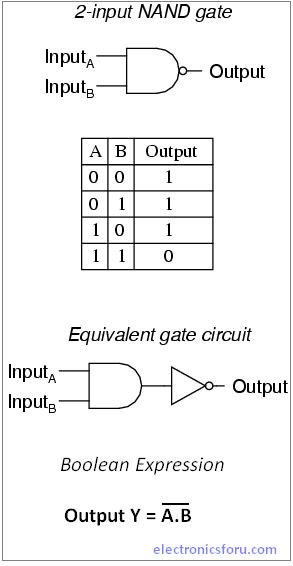
The Boolean expression for a logic NAND gate is denoted by a single dot or full stop symbol, (.) with an over line or bar, ( ‾ ) over the expression to signify the NOT or logical negation of AND gate.Ĭommonly used AND gate IC is 7400. The logic or Boolean expression for a logic NAND gate is that for Logical Addition, which is the opposite to the AND gate.

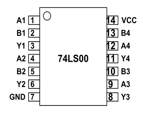
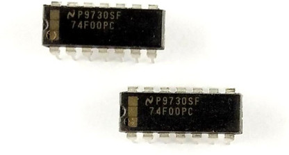
The Logic NAND Gate is the reverse or “c omplementary ” form of the AND gate. The NAND (Not – AND) gate has an output that is normally HIGH (1) and only goes LOW (0) when all of its inputs are HIGH (1). Therefore, 7400 is ideal for learning about digital logic as well as a “universal spare” when certain logic functions are needed. Its popularity is based on the fact that any logic gate function can be created using only NAND gates. It contains four independent two-input NAND gates. IC 7400, NAND gateħ400 IC is the most widely used TTL (Transistor-Transistor Logic) device in the world.

However, the parts listed above, and many others that are not listed, are still easily available today and are commonly found in a broad range of digital designs ranging from low-end to high-tech devices.
#Nand gate ic 7400 datasheet series
Other IC’s among 7400 series are no longer used as their specific function is rarely required as a separate chip in modern digital electronics designs. These are just a few of the full set of 7400 family members. Octal bus transceiver with tri-state outputs Quad D-type flip flops with complementary outputsįour-bit synchronous up/down binary counter Quad D-type flip-flops with complementary outputsĮight bit parallel out serial shift register Some most common members of the 7400 family and their functions are,īCD to seven-segment display decoder/driverĭual D-type positive edge triggered flip-flops Using a 7400 family IC, an engineer can design logic gates, flip-flops, counters, and buffers in individual packages and wire them together as desired to solve a specific problem.


 0 kommentar(er)
